Carbon Steel Piping: 12 Essential Components and Their Uses
Pipe, valves, strainers, flanges, elbows, tees, reducers, caps and supports in carbon steel piping: what each does and what to check in design and inspection.
By Syed Hasan25 Oct 20267 min read
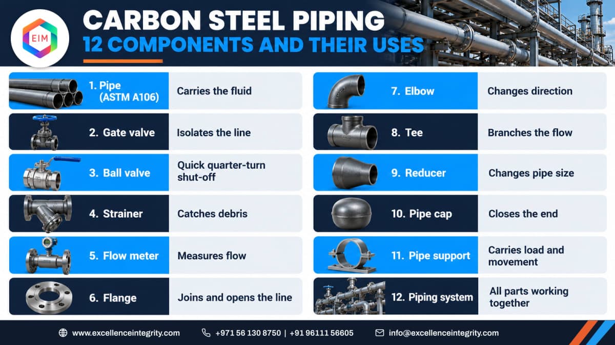
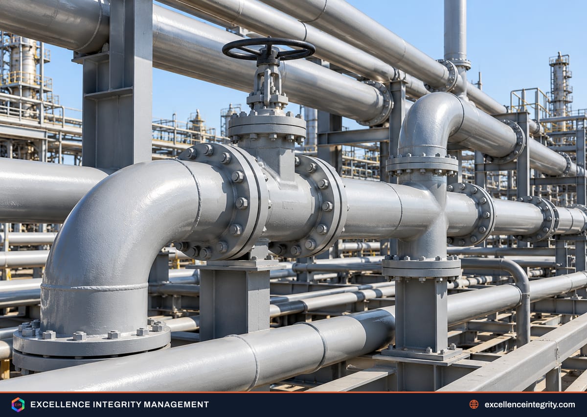
Walk any pipe rack in a refinery or power plant and most of what you see is carbon steel. It is strong, easy to weld, available everywhere and cheap compared with alloy or stainless, so it carries water, steam, hydrocarbons and utilities through most industrial plants. But a piping system is much more than pipe, and the components bolted and welded into it are where most leaks, blockages and inspection findings happen.
This article walks through twelve components you will find on almost every carbon steel line, what each one does, and what to watch for when you design, install or inspect it.
Why carbon steel for process piping
Carbon steel suits most process piping because it combines good strength with easy fabrication. It can be welded in the field, formed into fittings and repaired without exotic procedures. Its limits are just as important to know:
- Corrosion: it rusts in wet, oxygen-bearing or acidic service, so lines carry a corrosion allowance and often a coating or inhibitor.
- Temperature: at high temperature it loses strength and can suffer creep or graphitisation; at very low temperature ordinary grades become brittle, which is why impact-tested grades exist.
- Fluid compatibility: some services, such as concentrated acids, wet chlorides or high-purity water, need alloys or linings instead.
The twelve components and what they do
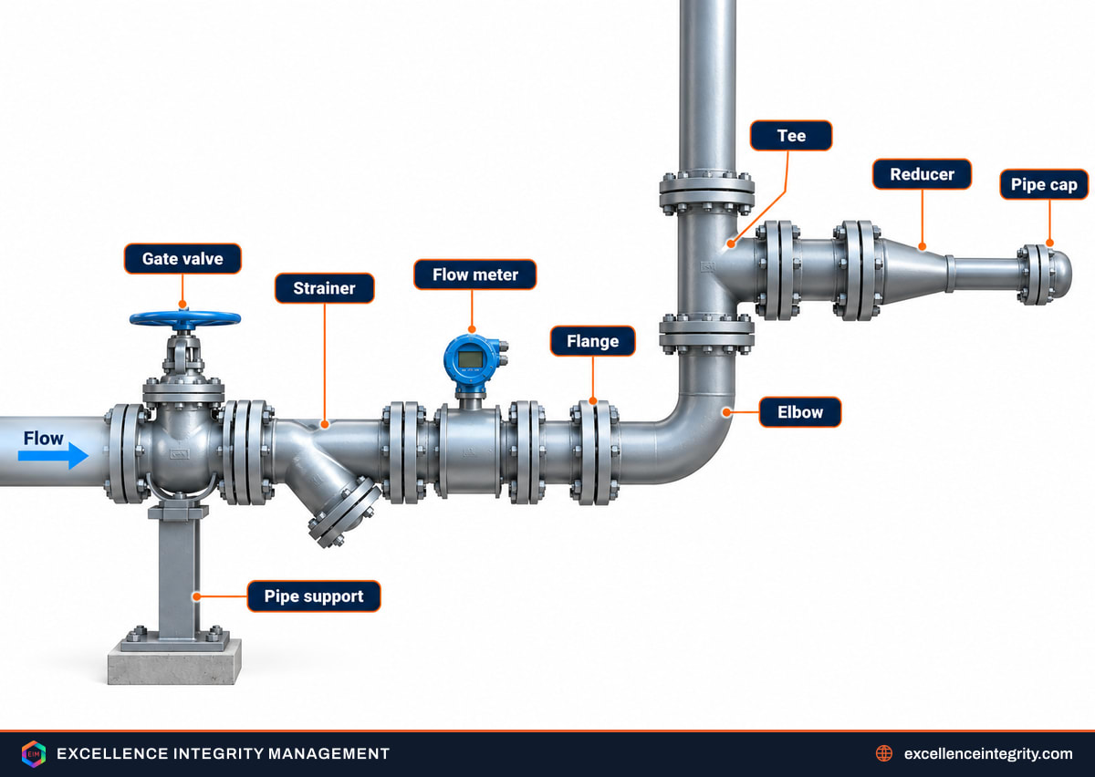
1. The pipe itself
Seamless carbon steel pipe to ASTM A106 is widely specified for high-temperature service, with ASTM A53 and API 5L common for general and pipeline service. The pipe schedule sets the wall thickness, and it is chosen from the design pressure and temperature plus the corrosion allowance, not from the nominal size alone.
2. Gate valve
A gate valve isolates a line. Fully open, the gate lifts clear of the flow, so pressure drop is low. It is not meant to throttle: running it part-open erodes the seats and gate, and it then stops sealing when you need it to.
3. Ball valve
A ball valve shuts off with a quarter turn, which makes it quick to operate and easy to see whether it is open or shut. Ball valves suit on-off duty in clean service and seal well with soft seats, within the seat material's temperature limit.
4. Strainer
Strainers catch weld slag, scale and debris before they reach pumps, control valves and instruments. Y-strainers are compact; basket strainers hold more dirt and suit bigger lines. A strainer that is never cleaned becomes a blockage, so a differential pressure gauge across it is worth fitting.
5. Flow meter
Flow meters, from orifice plates to magnetic, vortex and Coriolis meters, measure how much fluid passes for control and accounting. Most need a straight run of pipe upstream and downstream to read accurately, which has to be allowed for in the layout.
6. Flange
Flanges join pipes to valves, equipment and each other where the joint must come apart for maintenance or inspection. They are rated by pressure class, and the faces, gasket and stud bolts must all match that class. A flange joint is only as good as its assembly: even bolt tightening in the right sequence matters as much as the parts. Our guide to types of bolts and screws explains why flanges use stud bolts.
7. Elbow
Elbows change direction, most often by 45 or 90 degrees. Long-radius elbows give a gentler turn and lower pressure drop than short-radius ones. The outside of a bend sees the highest velocity, so elbows are a favourite place for erosion and are always on an inspector's thickness-reading list.
8. Tee
A tee creates a branch to split or combine flow. Equal tees keep the same size on all three ends; reducing tees step down on the branch. Where two streams of different temperature or chemistry meet, the tee becomes a mixing point that can suffer corrosion or thermal fatigue.
9. Reducer
Reducers join pipes of different diameters. Concentric reducers keep the centreline; eccentric reducers keep one side flat, which is why they are used at pump suctions, flat side up, so vapour cannot collect and cause cavitation.
10. Pipe cap
A cap closes the end of a pipe, for a future connection or a header end. Capped stubs are easy to forget, and stagnant liquid in them can make them a dead leg where corrosion runs faster than in the line that flows.
11. Pipe support
Supports carry the weight of pipe, fluid and insulation and control how the line moves when it heats up. Shoes, guides, anchors and spring hangers each do a different job; a missing or seized support overloads nozzles and fittings. The full family is covered in types of pipe supports.
12. The complete piping system
The last "component" is the system as a whole: pipe, fittings, valves, supports and instruments working together to move fluid safely. Problems at system level, such as vibration, water hammer, unsupported small-bore connections and thermal loads on equipment, are invisible if you look at one part at a time.
Design considerations that decide the details
| Consideration | What it affects |
|---|---|
| Design pressure and temperature | Pipe schedule, flange class, valve rating, material grade |
| Fluid and its chemistry | Whether carbon steel is suitable at all, lining or coating needs |
| Corrosion allowance | Extra wall added to the calculated thickness |
| Flow velocity | Pipe size, erosion at elbows and tees, noise and vibration |
| Material specification | Grade, impact testing for low temperature, traceability |
| Welding | Qualified procedures, heat treatment where required, NDT |
| Supports and flexibility | Loads on equipment nozzles, thermal movement |
| Design code | Rules for all of the above, such as ASME B31.3 for process piping |
Common mistakes with piping components
Most component problems on site come from a short list of habits that are easy to fall into:
- Throttling with a gate valve because it was the valve that happened to be there. Use a globe or control valve for regulation.
- Mixing flange classes or facings, such as a raised-face flange bolted to a flat-face one on cast iron equipment, which can crack the casting.
- Wrong material grade in the fitting: a fitting must match the pipe's specification and temperature rating, not just its size.
- Fitting a concentric reducer at a pump suction, leaving a pocket where vapour gathers.
- Leaving temporary strainers in place after commissioning until they block or collapse.
- Removing a support "for access" during maintenance and never putting it back.
Each of these is cheap to avoid at design or installation and expensive to find after start-up.
What inspectors look for in service
Once a carbon steel line is running, inspection focuses on where it loses wall and where it leaks:
- Thickness readings at elbows, tees, reducers and downstream of control valves, where flow is fastest or most turbulent.
- Dead legs and capped ends, where stagnant fluid speeds up corrosion.
- Corrosion under insulation, especially on lines cycling through the 0 to 175 degree Celsius range.
- Flange leaks, gasket weeps and corroded stud bolts.
- Supports that have corroded at the contact point, seized, or let the line sag.
- Small-bore connections that vibrate, a common source of fatigue cracks.
Valves deserve their own attention: a gate valve that has been throttled, or packing that weeps at the stem, will not hold when isolation matters. Our article on types of gland packing covers stem sealing.

Going further
In-service inspection of process piping, from thickness surveys to repairs and fitness for continued service, is what the API 570 piping inspector certification preparation covers. Damage mechanisms such as erosion and corrosion under insulation are in the API 571 preparation. Questions about a specific line? Get in touch.
Enjoyed the question? See more practice for API 570 Piping Inspector