Shaft Alignment Tools and Methods: From Straight Edge to Laser
Shaft alignment tools compared, from feeler gauges and dial indicators to laser systems, plus the soft foot and thermal growth checks that come first.
By Harish Haseeb22 Nov 20268 min read

A pump that keeps eating bearings, a coupling insert that cracks every few months, a motor that runs hot on one end. Very often the root cause is the same: the two shafts are not sitting on one straight line. Misalignment loads bearings, seals and couplings in ways they were never designed for, and it does it quietly until something gives.
This post explains the tools maintenance teams use to check and correct shaft alignment, what each one is good for, and the order of work that gets a reliable result. It is written for the engineer who has to choose between a dial indicator and a laser system, and wants to know what to check before either one goes on the shaft.
What misalignment actually is
Two shafts can be out of line in two ways, and usually both at once. Parallel (offset) misalignment means the centrelines are parallel but displaced, one higher or to the side of the other. Angular misalignment means the centrelines meet at an angle. Each is measured in the vertical and the horizontal plane, so a full check gives four values.
Alignment is always judged at the coupling, but the correction is made at the feet of the moveable machine, usually the motor. That is why alignment readings are turned into shim changes at the front and rear feet and horizontal moves at each foot. Get the geometry clear in your head and every tool below makes sense.
The basic hand tools
Straight edge. A rigid reference laid across the coupling hubs or pulley faces. It is the quickest rough check and fine for a first look or for low-speed equipment, but it cannot give the accuracy rotating machinery needs for final alignment.
Feeler gauge. A set of thin blades of known thickness. Used to measure the gap between coupling faces at several points (a rough angular check), to check clearances, and, very importantly, to check for soft foot under machine feet.
Precision level. Measures small deviations from horizontal or vertical. Its main job in alignment work is setting machine foundations, pump bases and motor mounting plates level before the shafts are aligned. A digital inclinometer does a similar job electronically and reads angles directly, which helps when checking machine-bed angles and installation positions.
Dial indicator methods
A dial indicator measures small movements with a plunger and a pointer. Clamped to one shaft with its plunger on the other hub, it shows how far the other shaft's position changes as both shafts are turned together. A dial test indicator (DTI) is the more sensitive lever-type version, used for runout checks and precision setups.
Two methods of dial indicator alignment are common:
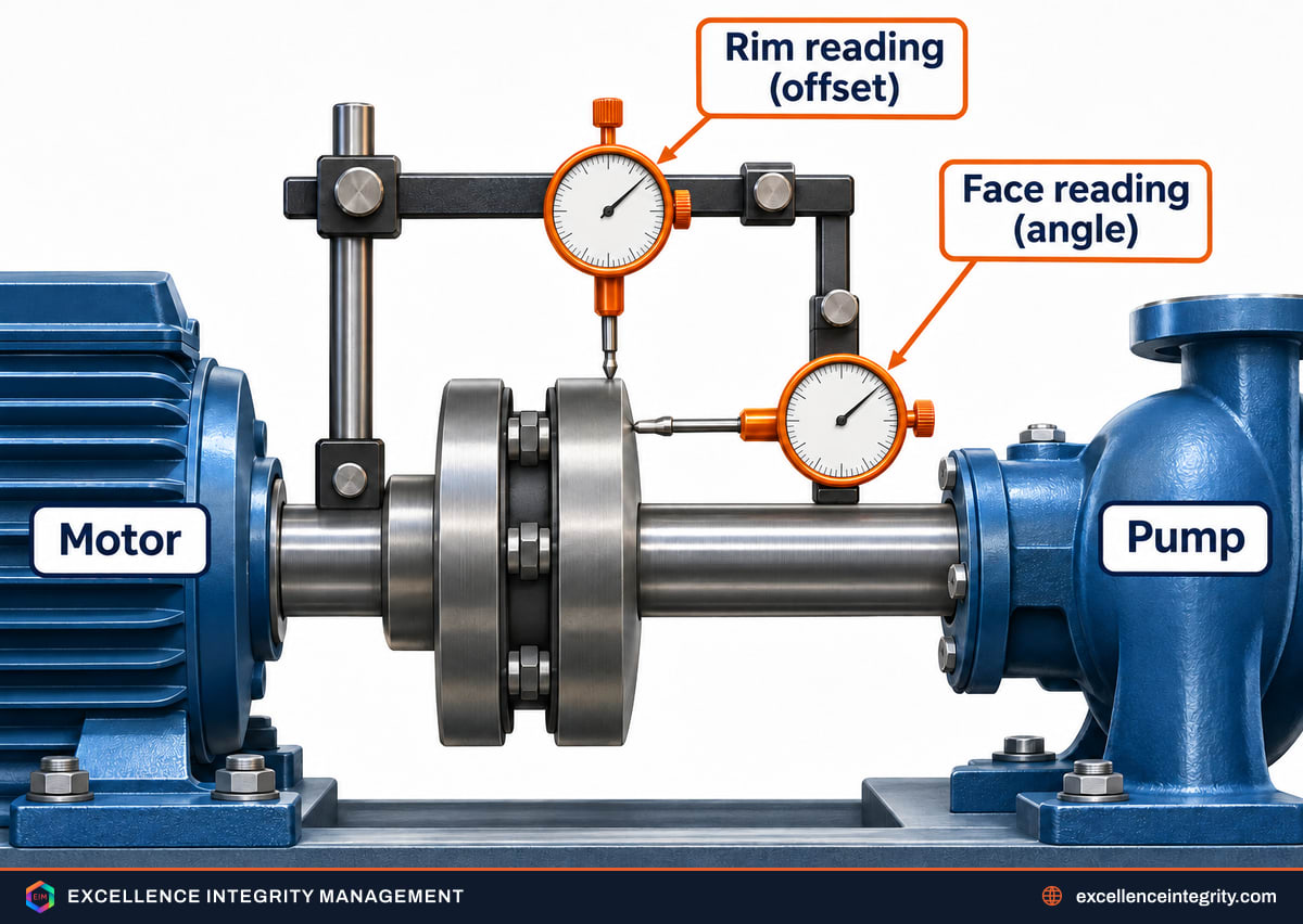
- Rim and face. One indicator reads the rim (outer diameter) of the opposite hub for offset, and another reads the face for angle. A rim and face gauge holds both. Rim and face alignment suits couplings with a reasonable face diameter and short spans.
- Reverse indicator. Two indicators read the rims of both hubs from opposite shafts. It is generally preferred where the face is small or the spacer is long, and it is less affected by axial float of the shafts.
Dial methods are accurate in skilled hands, cost little and need no batteries. Their weak points are bracket sag (the bracket bends under its own weight, which must be measured and corrected for), reading errors, and the time needed to work out the corrections by hand or by graph.
Laser alignment systems
A laser alignment tool replaces the indicators with a laser emitter and a detector, one on each shaft. As the shafts turn, the system measures how the beam moves on the detector and calculates offset and angle in both planes, then shows the shim and move needed at each foot.
The practical advantages are speed, no bracket sag, live readings while you move the machine, and a saved report for the maintenance record. Many systems also include a soft foot check and thermal growth offsets. The disadvantages are cost, the need for charged batteries and a clear line of sight, and the risk of trusting the screen without understanding the numbers. A technician who knows the dial methods will catch a bad laser reading that someone who only knows the laser will not.

Pulleys, long shafts and optics
Belt drives need their own check because the pulleys must sit in one plane. A pulley alignment tool uses a laser or optical reference across the pulley faces to show offset and twist on fans, blowers, compressors and conveyors. Misaligned pulleys wear belts and sheaves quickly and load the bearings sideways.
For long shaft trains and precision installations, an optical alignment scope sets components against a fixed optical reference line. It is specialist equipment, used where the distances are long or the accuracy demanded is high.
Checking the result: heat and vibration
Two condition monitoring tools close the loop. A thermal imaging camera shows temperature differences, so an overheating bearing, motor or coupling stands out against the rest of the machine. A vibration analyzer measures vibration and helps tell misalignment apart from imbalance, looseness and bearing defects.
Misalignment often shows up in vibration readings with strong components at running speed and its multiples, frequently with high axial vibration. Taking readings before and after alignment is the simplest proof that the job worked, and the after reading becomes the baseline for the next visit.
The order of work that gets it right
Most failed alignments are not tool problems. They come from skipping the checks before the tool goes on. A sound sequence looks like this:
- Safety and isolation. Lock out and tag out both machines and confirm zero energy before touching the coupling.
- Foundation and base. Check the baseplate is sound, the grout is not cracked and the bolts are tight.
- Coupling condition. Look for worn inserts, damaged teeth or a loose hub. Aligning a damaged coupling wastes the effort.
- Runout. Check shaft and hub runout with a dial test indicator. A bent shaft or eccentric hub makes alignment readings meaningless.
- Soft foot. Loosen each foot in turn and measure the movement. Correct it with shims before aligning, or the machine will move every time the bolts are tightened.
- Thermal growth. Find out how much each machine grows when hot, from the equipment maker or from measurement, and set the cold targets to allow for it.
- Measure, correct, measure again. Vertical corrections first with shims, then horizontal moves, then a final reading with all bolts tightened to their correct torque.
- Verify in service. Check vibration and bearing temperatures once the machine is running at its normal load.
The tolerances themselves come from the equipment manufacturer or your site standard, and they usually tighten as running speed rises. Do not borrow a number from a different machine.

Choosing between shaft alignment tools
| Tool | Best use | Main limitation |
|---|---|---|
| Straight edge, feeler gauge | Rough checks, soft foot, gaps | Not accurate enough for final alignment |
| Precision level, inclinometer | Levelling bases and machine beds | Does not measure shaft-to-shaft position |
| Dial indicator (rim and face, reverse) | Accurate alignment at low cost | Bracket sag, slower, skill dependent |
| Laser system | Fast, repeatable alignment with records | Cost, batteries, line of sight |
| Pulley alignment tool | Belt drives | Pulleys only |
| Thermal camera, vibration analyzer | Proving the result in service | Shows the symptom, not the correction |
Correct shaft alignment means less vibration, lower maintenance cost and longer equipment life. It is one of the cheapest reliability improvements a plant can make, and one of the easiest to undo with a rushed job.
Frequently asked questions
What are the two types of shaft misalignment?
Parallel, or offset, misalignment means the two centrelines are parallel but displaced, one higher or to the side of the other. Angular misalignment means the centrelines meet at an angle. Most machines have some of both, and each is measured in the vertical and the horizontal plane, so a full check gives four values.
Is laser alignment better than a dial indicator?
A laser system is faster, has no bracket sag, gives live readings while you move the machine and saves a report. Dial indicators cost little, need no batteries and are accurate in skilled hands, but they are slower. A technician who understands the dial methods is also better at spotting a bad laser reading.
What is soft foot and how do you check it?
Soft foot is a machine foot that moves when its bolt is loosened, so the machine shifts every time the bolts are tightened. Loosen each foot in turn and measure the movement, using a feeler gauge or the check built into many laser systems. Correct it with shims before you align, not after.
What is the tolerance for shaft alignment?
Take the tolerance from the equipment manufacturer or your site standard, not from a different machine. Tolerances usually get tighter as running speed rises, so a high-speed compressor needs a closer result than a slow conveyor drive. Set the cold targets to allow for thermal growth, then confirm with vibration and bearing temperatures in service.
Where to go from here
Alignment sits inside a wider set of rotating equipment skills: diagnosing vibration, reading bearing damage and setting up a maintenance strategy that catches problems early. The rotating equipment maintenance and troubleshooting course covers the hands-on side, and rotating equipment maintenance in oil and gas gives the bigger picture. If you are moving into reliability leadership, the SMRP CMRP exam preparation and the reliability and asset integrity programme take it further.
Exam preparation
Preparing for SMRP CMRP?
Practise with exam-style questions, timed mocks and study notes. 1,448 questions in the bank.