Inside a Shell and Tube Heat Exchanger: The Parts That Do the Real Work
A practical walk through the shell, tube bundle, tube sheet, baffles and tie rods, and why each one matters on the plant floor.
EIM Editorial Team14 Oct 202614 min read
Walk through any refinery, petrochemical unit, power plant or gas processing facility and you will find heat exchangers almost everywhere you look. Crude preheat trains, overhead condensers, lube oil coolers, reboilers, feed and effluent exchangers. They are some of the most common pieces of equipment on site, and the shell and tube design is still the one you will run into most often.
The job sounds simple. Take heat from one fluid and give it to another, without letting the two fluids touch. Getting that done reliably for twenty or thirty years, under pressure, with dirty or corrosive fluids, is where the engineering comes in. Most of that engineering sits inside the shell where you never see it during normal operation.
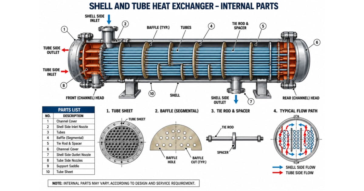
In this post we will open the exchanger up, piece by piece, and look at what each internal part does, why it is designed the way it is, and what tends to go wrong with it in service.
How a Shell and Tube Exchanger Works
Picture a long pressure vessel (the shell) with a bundle of small diameter tubes running through it. One fluid flows inside the tubes. The other flows through the shell, around the outside of those tubes. Heat moves through the tube wall from the hotter fluid to the colder one. That is really all there is to the principle.
In industry, we just call these the two "sides" of the exchanger:
- Tube side: the fluid that enters through the front channel head, travels through the tubes, and leaves through the channel again (or through the rear head, depending on the design).
- Shell side: the fluid that enters through the shell inlet nozzle, works its way across and along the tube bundle, and leaves through the shell outlet nozzle.
Which fluid goes where is a real design decision, not a coin toss. As a general habit, designers put the dirtier, more corrosive or higher pressure fluid on the tube side. Tubes are far easier to clean than the shell side, a corrosive fluid in the tubes means only the tubes and channel need expensive alloy, and a small diameter tube handles high pressure much more cheaply than a large diameter shell. Viscous fluids and fluids with a low allowable pressure drop usually do better on the shell side.
Key Internal Components
1. The Shell
The shell is the outer pressure vessel that wraps around the whole tube bundle. It holds the shell-side fluid as it flows over the outside of the tubes, and it has to be designed for that fluid's pressure and temperature, normally to ASME Section VIII along with TEMA and, in refinery service, API 660.
Shells are usually made from rolled plate or, for smaller sizes, pipe. The inside diameter has to be held fairly tight because the gap between the shell and the baffles directly affects how much fluid sneaks around the baffles instead of crossing the tubes. A shell that is out of round or has a lot of weld protrusion inside will quietly cost you performance.
In the field, the area right under the shell inlet nozzle takes a beating. High velocity fluid hits the first few rows of tubes and the shell wall at that point, which is why you often see an impingement plate or a distribution belt fitted there.
2. Front and Rear Channel Heads
At each end of the exchanger sits a head. The front (channel) head receives the tube-side fluid through its inlet nozzle and directs it into the tubes. Inside, it usually has a pass partition plate that splits the channel into sections, so the fluid is forced to go down one group of tubes and come back through another. Each trip through the bundle is called a pass. Two, four, six and even eight pass designs are common.
The channel cover bolts onto the end of the channel. On the popular TEMA type A front end, you can take that cover off and get direct access to the tube ends for inspection or cleaning without disturbing the piping. That small detail saves a lot of time during a shutdown.
The rear head does the same turning job at the far end. Depending on the design it can be a fixed head, a floating head that lets the bundle grow with temperature, or simply the bends of a U-tube bundle.
3. Nozzles
There are four main nozzles on a typical exchanger: shell-side inlet and outlet, and tube-side inlet and outlet. Their size is driven by allowable velocity and pressure drop. They look like an afterthought on a drawing, but nozzle velocity is a real cause of erosion and tube vibration damage near the inlet, so nozzle sizing and the use of impingement protection get checked carefully during design review.
4. Tube Bundle and Tube Sheet
The tubes are where the heat transfer actually happens. A bundle can hold anything from a few dozen tubes to several thousand. Common sizes are 3/4 inch and 1 inch outside diameter, made of carbon steel, stainless steel, copper alloys, duplex, titanium or other alloys depending on what is flowing through them.
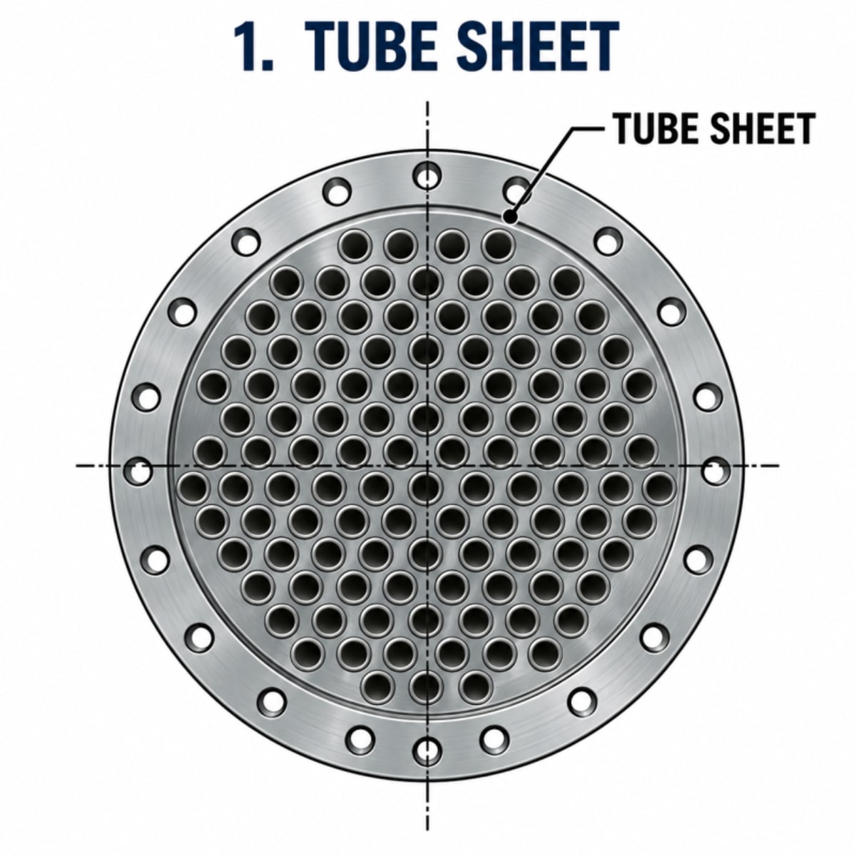
The tube sheet is a thick, heavily drilled plate that holds the ends of every tube. It is also the wall that separates the shell-side fluid from the tube-side fluid, so if a joint here leaks, the two fluids mix. That is why the tube sheet is one of the most critical parts of the whole exchanger.
A few things worth knowing about tube sheets:
- Tube layout: holes are drilled in a triangular or square pitch. Triangular fits more tubes into the same shell, which means more surface area. Square pitch leaves straight cleaning lanes between rows, so it is preferred when the shell side is dirty and needs mechanical cleaning.
- Tube-to-tubesheet joints: tubes are fixed by expanding (rolling) them into the holes, by seal or strength welding, or by both. Leaks at these joints are one of the most common exchanger problems found during turnarounds.
- Multiple passes: working together with the pass partition plates in the channel, the tube sheet layout routes the tube-side fluid through the bundle several times. More passes mean higher velocity in the tubes, better heat transfer and less fouling, at the cost of a higher pressure drop.
5. Baffles (Segmental)
If you left the shell empty apart from the tubes, the shell-side fluid would simply run straight from inlet to outlet along the path of least resistance. It would hardly touch most of the tubes, and heat transfer would be poor. Baffles fix that.
A segmental baffle is a circular plate, drilled to let the tubes pass through, with a segment cut off one side. That cut-off area is the baffle window. Baffles are installed with the windows alternating top and bottom (or side to side), so the shell-side fluid is forced to flow across the bundle, turn through the window, cross the bundle again in the opposite direction, and so on along the full length of the shell.
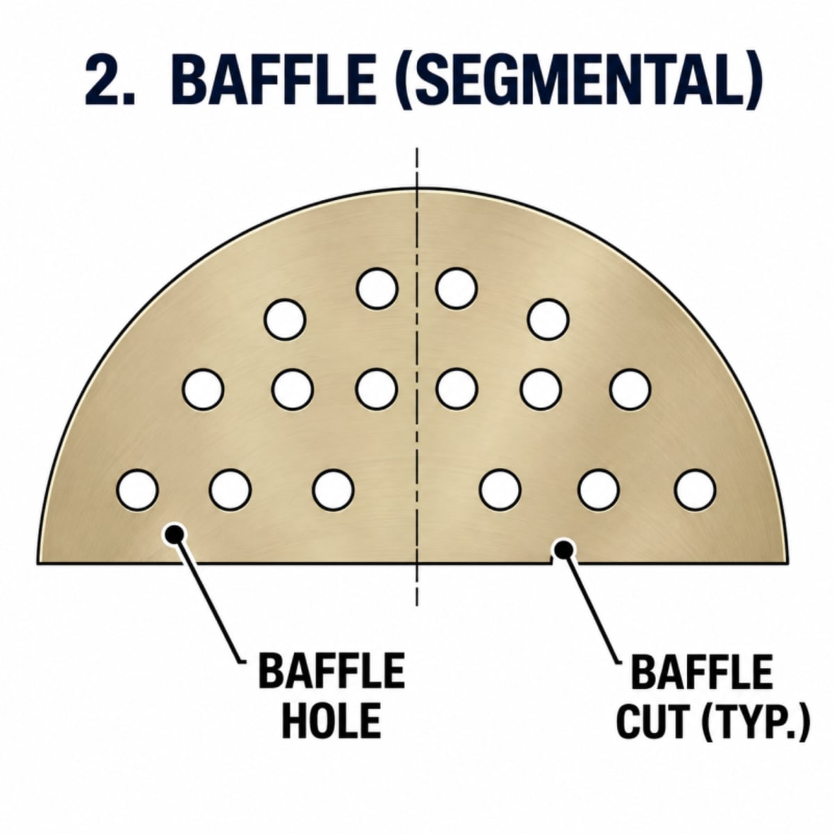
This back and forth crossflow does two useful things. It creates turbulence around the tubes, which breaks up the slow moving layer of fluid that clings to the tube surface and resists heat flow. And it keeps the velocity up, which helps reduce fouling. The result is a big jump in the shell-side heat transfer coefficient compared to a plain, unbaffled shell.
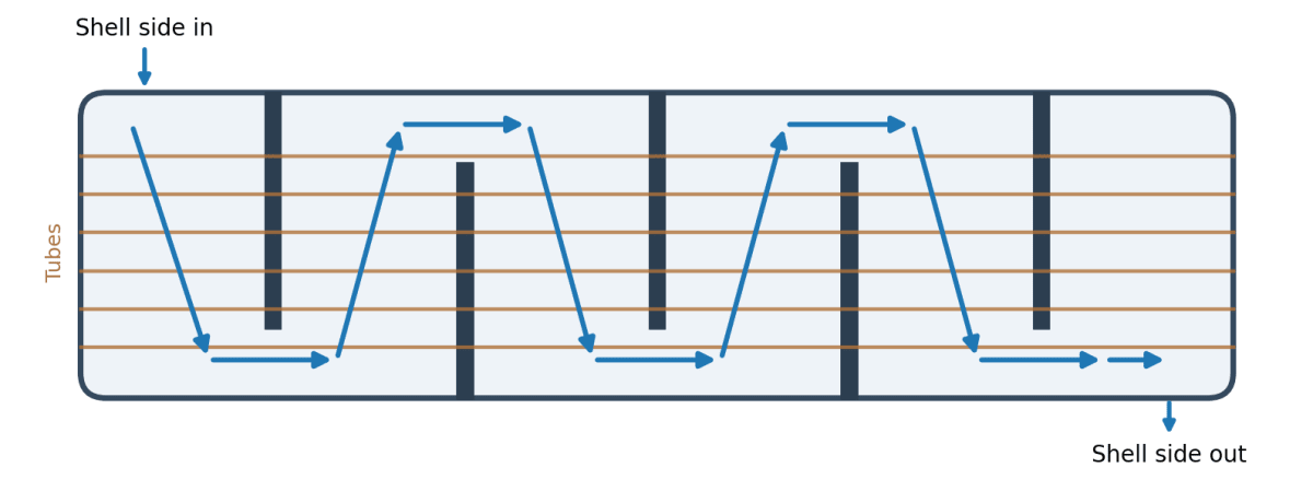
Baffles have a second job that is just as important. They physically support the tubes along their length. A long, thin tube with fluid rushing past it can start to vibrate, and if the unsupported span is too long, that vibration will wear the tube against the baffle holes until it fails. Proper baffle spacing keeps the unsupported span short enough to avoid that.
Two design numbers you will hear about all the time:
- Baffle cut: the height of the window as a percentage of shell diameter. Most designs fall somewhere around 20 to 35 percent, with 25 percent being a very common choice. Cut too small and pressure drop climbs. Cut too large and the flow stops crossing the tubes properly.
- Baffle spacing: the distance between baffles. Closer spacing gives better heat transfer and better tube support but higher pressure drop. Wider spacing does the opposite. TEMA sets minimum spacing and maximum unsupported tube span limits that designers have to work within.
There are other baffle styles too, such as double segmental, disc and doughnut, rod baffles and helical baffles, mostly used to lower pressure drop or deal with vibration. Single segmental is still the workhorse, and it is the type shown in our diagram.
6. Tie Rods and Spacers
Baffles do not float freely inside the bundle. They are held in position by tie rods and spacers. The tie rod is a long round bar threaded into the stationary tube sheet at one end. Spacers are short lengths of pipe that slip over the tie rod between each pair of baffles. Stack them up in order (spacer, baffle, spacer, baffle) and tighten a nut at the far end, and you have a rigid frame that locks every baffle at exactly the right spacing.
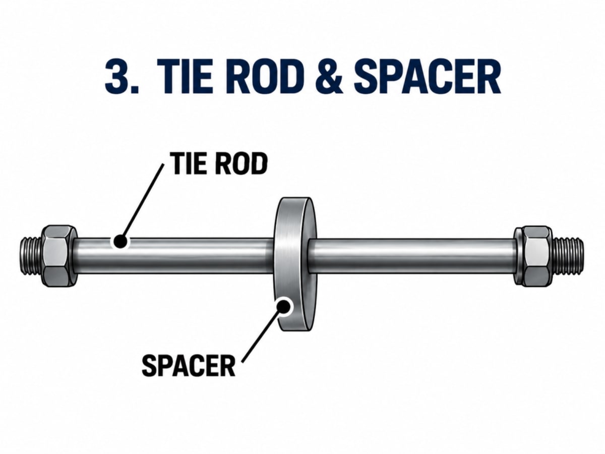
That precise alignment matters more than it might seem. If baffles shift, tube holes stop lining up, tubes get pinched or bent, and the spacing that the thermal design was based on is gone. The tie rod and spacer assembly also gives the bundle enough stiffness to be pulled out of the shell during maintenance without the baffles collapsing or twisting.
TEMA specifies the minimum number and diameter of tie rods based on shell size, starting at four rods for smaller shells and increasing as the shell gets larger. They are usually placed near the edge of the bundle and around the baffle windows, where they also help block bypass lanes.
7. Support Saddles
The saddles under the shell carry the weight of the exchanger, the fluid inside it and any bundle pulling loads. On most horizontal units one saddle is fixed and the other is slotted so it can slide. As the shell heats up and grows, the sliding saddle lets it move instead of pushing hard against the piping or the foundation. If that sliding saddle seizes from rust or paint, you can end up with cracked nozzles or strained piping, so it is worth checking during inspections.
Putting It Together: The Typical Flow Path
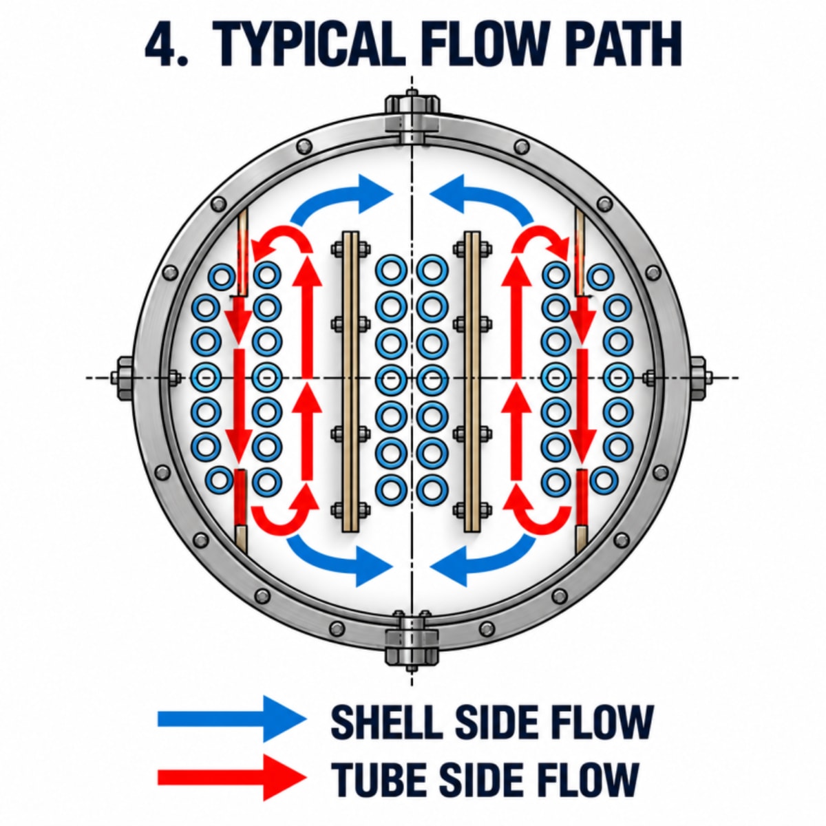
Follow both fluids through the exchanger and the role of each part becomes clear. The tube-side fluid enters the front channel, gets directed by the pass partition into the first group of tubes, travels to the rear head, turns around and comes back through the next group, and finally leaves through the channel outlet. Meanwhile, the shell-side fluid enters at the top, gets turned by the first baffle, sweeps across the bundle, passes through the window, sweeps back across, and keeps zigzagging until it reaches the outlet nozzle.
The two fluids never meet, but they spend a long time very close to each other, separated only by a thin tube wall. That combination of a large surface area, controlled turbulence and multiple passes is what makes the shell and tube design so effective and so flexible.
Quick Reference: Components, Functions and Common Problems
| Component | Main Function | What Goes Wrong in Service |
|---|---|---|
| Shell | Holds the shell-side fluid and contains the pressure | Corrosion, thinning near the inlet nozzle, erosion |
| Channel heads and covers | Collect and distribute tube-side fluid between passes | Pass partition plate damage, gasket leaks |
| Nozzles | Bring each fluid in and out | Erosion at inlet, cracking at the nozzle weld |
| Tubes | Carry the tube-side fluid and do the actual heat transfer | Fouling, pitting, vibration wear, leaks |
| Tube sheet | Holds the tube ends and separates the two fluids | Leaking tube-to-tubesheet joints, ligament cracking |
| Segmental baffles | Push shell-side flow across the tubes and support them | Hole wear, loose fit, bypass around the edges |
| Tie rods and spacers | Keep baffles at the correct spacing and position | Loose nuts, corrosion, broken rods |
| Support saddles | Carry the weight and allow for thermal movement | Seized sliding saddle, cracked welds |
What Inspectors and Maintenance Teams Look For
Knowing the internal parts is one thing. Knowing how they fail is what really helps on the job. Some of the issues that show up again and again during shutdowns:
- Fouling: scale, coke, biological growth or sludge builds up on tube surfaces and slowly kills heat transfer. Rising pressure drop and falling outlet temperatures are the usual early signs. Our guide to fouling in heat exchangers covers the causes, prevention and cleaning methods.
- Tube leaks: caused by corrosion, erosion, vibration or cracking. Eddy current testing, IRIS and hydrotesting are commonly used to find them, and leaking tubes are plugged or the bundle is retubed.
- Baffle damage: tube holes wear oversize, baffles thin out from corrosion or the bundle gets damaged during pulling. Loose baffles mean more vibration and more bypass flow.
- Joint and gasket leaks: at the tube-to-tubesheet joints, channel cover gaskets and floating head gaskets, often linked to thermal cycling.
- Damage mechanisms: things like under deposit corrosion, galvanic corrosion, erosion and stress corrosion cracking. API 571 covers these in detail and is well worth knowing if you work around exchangers.
Final Thoughts
A shell and tube heat exchanger looks like a plain steel cylinder from the outside, but every part inside it has a job. The shell contains the pressure. The tube sheet and tubes keep the fluids apart while letting heat through. The channel heads route the tube-side flow through multiple passes. The baffles create the crossflow and turbulence that make the shell side efficient, while holding the tubes steady. And the tie rods and spacers quietly keep everything lined up so the design actually performs the way it was calculated.
Once you understand how these pieces work together, everything else about exchangers, from thermal design to inspection planning to troubleshooting a unit that has lost performance, starts to make a lot more sense.
Frequently Asked Questions
What is the purpose of baffles in a shell and tube heat exchanger?
Baffles do two jobs. They force the shell-side fluid to flow across the tubes instead of straight along them, which creates turbulence and improves heat transfer. They also support the tubes along their length so they do not sag or vibrate and wear out.
What is baffle cut in a heat exchanger?
Baffle cut is the height of the opening (the window) cut from a segmental baffle, expressed as a percentage of the shell inside diameter. Most designs use somewhere between 20 and 35 percent, with 25 percent being very common. It controls how the shell-side fluid turns from one baffle space to the next.
What is the difference between a tube sheet and a baffle?
The tube sheet is a thick plate at the end of the bundle that holds the tube ends and seals the shell-side fluid from the tube-side fluid. A baffle is a thinner plate inside the shell that guides the shell-side flow and supports the tubes. The tube sheet is a pressure boundary. The baffle is not.
Which fluid should go on the tube side?
As a general rule, the dirtier, more corrosive or higher pressure fluid goes on the tube side. Tubes are easier to clean, only the tubes and channel need expensive alloy, and small tubes handle pressure more cheaply than a large shell. Viscous fluids and fluids with a low allowable pressure drop usually go on the shell side.
Why are tie rods and spacers used in a heat exchanger?
Tie rods and spacers lock the baffles at the correct spacing and keep them aligned with the tube holes. They also make the bundle rigid enough to be pulled out of the shell for cleaning and inspection without the baffles shifting.
How do you find a leaking tube in a heat exchanger?
Common methods include a shell-side hydrotest or pneumatic test to spot which tube ends leak, and non-destructive tests such as eddy current testing or IRIS to measure wall loss along the tubes. Leaking or badly thinned tubes are then plugged or the bundle is retubed.
Building your career in plant integrity? Excellence Integrity Management offers self-paced exam preparation and live courses for API, AMPP and CSWIP certifications, covering pressure equipment, damage mechanisms and inspection practice. For exchangers in particular, see the Heat Exchanger Inspection & Maintenance live course and the self-paced Heat Exchanger Integrity & Tube Bundle Assessment programme, or reach us at info@excellenceintegrity.com.