Reading Weld Radiographs: What Common Defects Look Like, and What to Check First
How to read a weld radiograph: what porosity, slag, lack of fusion, cracks and undercut look like, and the checks to make on the film first.
By Syed Hasan8 Nov 20266 min read
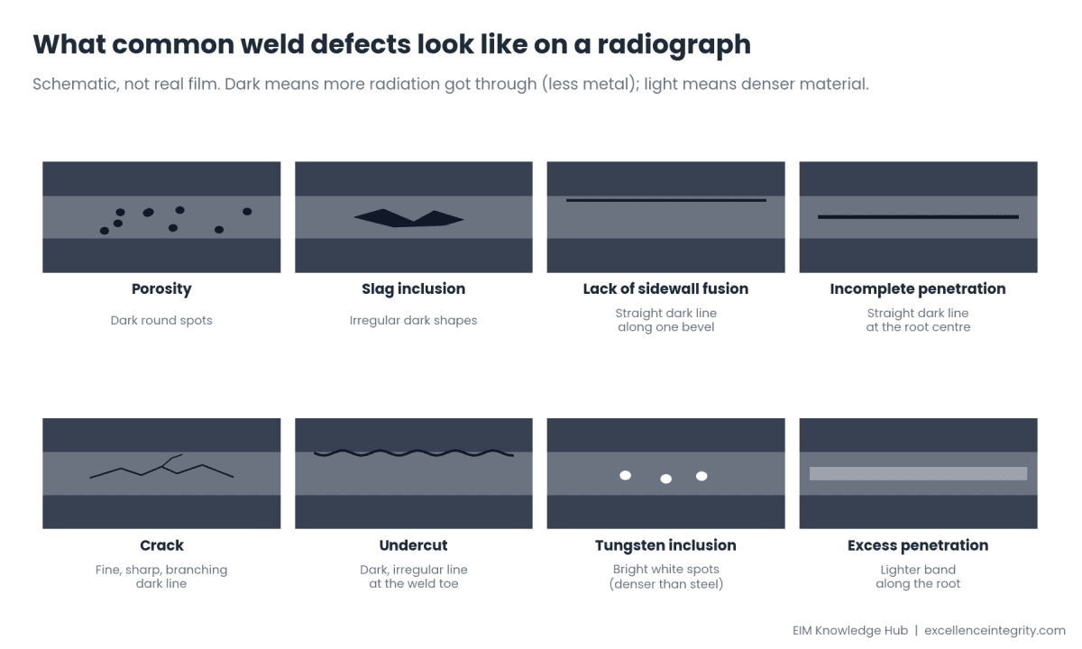
A radiograph is a shadow picture of a weld. Radiation passes through the steel and darkens the film or detector wherever more of it gets through, so voids show dark and dense inclusions show light. Reading one well is a skill every welding inspector is expected to have, and the fastest way to learn it is to know what each common defect looks like, and what to check before you trust the image at all.
Short answer: Before interpreting, check the identification, the image quality indicator (IQI), the density and any artifacts. Then read the weld: porosity shows as dark round spots, slag as irregular dark shapes, lack of fusion and incomplete penetration as straight dark lines, cracks as fine sharp lines, undercut as dark lines at the toe, and tungsten inclusions as bright spots. Acceptance always comes from the governing code.
Light and dark: the one rule to remember
More radiation reaching the film makes it darker. So anything that removes metal from the beam path (a gas pore, a slag pocket, a crack, an unfused gap) shows darker than the surrounding weld. Anything denser than steel, such as a tungsten inclusion, or extra metal, such as excess penetration, shows lighter. The weld itself usually looks lighter than the parent plate because the reinforcement adds thickness.
Check the film before you judge the weld
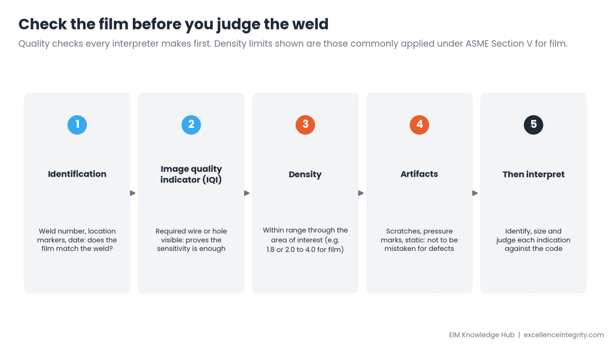
- Identification. Weld number, location markers and date must match the weld and the drawing. Without location markers you cannot find what you see.
- Image quality indicator (IQI). The required wire or hole must be visible. It proves the technique was sensitive enough to see defects of the size that matters.
- Density. The film must be within the allowed density range through the area of interest. Under ASME Section V, film density is commonly required to be at least 1.8 for X-ray and 2.0 for gamma ray, and no more than 4.0.
- Artifacts. Scratches, pressure marks, static discharges, water marks and processing defects can look like weld defects. Learn to recognise them.
- Coverage. The whole length to be examined must be on film, with the overlap the procedure requires.
What common defects look like
| Defect | How it looks | Typical cause |
|---|---|---|
| Porosity | Dark, round, sharp-edged spots, single, scattered or clustered | Contamination, moisture, poor gas shielding |
| Slag inclusion | Irregular dark shapes, often elongated along the weld | Poor inter-pass cleaning, wrong technique |
| Lack of sidewall fusion | Straight, dark line, often offset to one side along the bevel | Low heat input, wrong angle, poor access |
| Incomplete penetration | Straight, dark line along the centre of the root | Root gap too small, low current, poor fit-up |
| Crack | Fine, sharp, often branching dark line; may be faint | Restraint, hydrogen, hardness, poor procedure |
| Undercut | Dark, irregular line along the weld toe | Excessive current or travel speed |
| Tungsten inclusion | Bright white spots or fragments | Tungsten electrode touching the weld pool (TIG) |
| Excess penetration / burn-through | Lighter band at the root; burn-through as a dark spot with a light rim | Excessive heat or root gap |
Two pairs cause most confusion. Lack of fusion vs incomplete penetration: both are straight dark lines, but incomplete penetration usually sits at the root centre while sidewall lack of fusion follows the bevel to one side. Slag vs porosity: porosity is round with sharp edges; slag is irregular. When in doubt, a second exposure at a different angle helps.
Acceptance comes from the code, not the picture
Identifying an indication is only half the job. Whether it is acceptable depends on the governing code and the type of examination: for example ASME Section VIII Division 1 (UW-51 for full radiography and UW-52 for spot), ASME B31.3 for process piping, API 1104 for pipelines, or ISO 10675 with ISO 5817 quality levels under ISO/EN specifications. Cracks and lack of fusion are generally rejectable under the common codes; rounded indications and slag are judged by size, length and spacing. Always work from the edition and acceptance table your contract specifies.
Digital radiography
Computed radiography (CR) and digital detector arrays (DR) are now common. The same principles apply, but image quality is judged by different measures, and procedures must be qualified for digital use under the governing code. Brightness and contrast can be adjusted on screen, which helps interpretation but must not be used to hide a poor exposure.
Five interpretation mistakes
- Skipping the IQI check and accepting a film that could not show the defects that matter.
- Calling artifacts defects, or defects artifacts. Check both sides of the film and the processing.
- Judging against the wrong code or edition.
- Ignoring faint linear indications. Cracks can be very faint, especially at an angle to the beam.
- Interpreting without the weld map. Without knowing where you are on the weld, you cannot report a usable location.
Learn more with EIM
EIM's live Welding Repair and Inspection course with Mr. Deepak Rawtal, Senior Metallurgical Inspection Engineer with 45 years in metallurgical and materials testing, covers welding quality and terminology, defects and their causes and prevention, radiographic interpretation, visual inspection and weld repair techniques, with a practical workshop and case studies.
Next batch: 28 to 31 December 2026, Monday to Thursday, 19:00 to 21:00 UAE time.
4 sessions of 2 hours, with an EIM certificate of completion. See the course
Preparing for a welding inspector certification? EIM's self-paced preparation for CSWIP 3.0, 3.1 and 3.2 includes a question bank, practice mode with explanations, timed mock tests, study notes and flashcards, with one year of access. Not sure where to start? Read CSWIP 3.0 or 3.1 first? EIM is an independent training provider.
Frequently asked questions
Why do voids appear dark on a radiograph?
Less metal in the beam path lets more radiation through to the film or detector, which darkens it. Dense inclusions do the opposite and appear light.
What is an IQI?
An image quality indicator: a wire set or hole plaque placed on the weld during exposure. Seeing the required wire or hole proves the radiograph has enough sensitivity.
What film density is acceptable?
Under ASME Section V, film density is commonly required to be at least 1.8 for X-ray and 2.0 for gamma ray, and no more than 4.0, through the area of interest. Check your code and procedure.
How do I tell lack of fusion from incomplete penetration?
Both appear as straight dark lines. Incomplete penetration usually lies at the centre of the root; lack of sidewall fusion follows the bevel to one side.
Are cracks always rejectable?
Under the common fabrication codes, cracks are generally rejectable regardless of size. Check the acceptance criteria of your governing code.
Sources
- ASME Boiler and Pressure Vessel Code, Section V, Article 2 (radiographic examination) and Section VIII Division 1, UW-51 and UW-52. Cited, not quoted.
- ASME B31.3, API 1104 and ISO 10675 acceptance criteria. Cited by name only.
- Defect schematics prepared by EIM. Checked 7 October 2026.