Thermal Fatigue: Damage Mechanism of the Week
Thermal fatigue explained: how temperature cycling cracks equipment, where it strikes (mix points, desuperheaters, coke drums) and how to prevent it.
Written by Nilanjan SenReviewed by Deepak Rawtal
Published 20 Oct 2026Reviewed 7 Oct 20263 min read
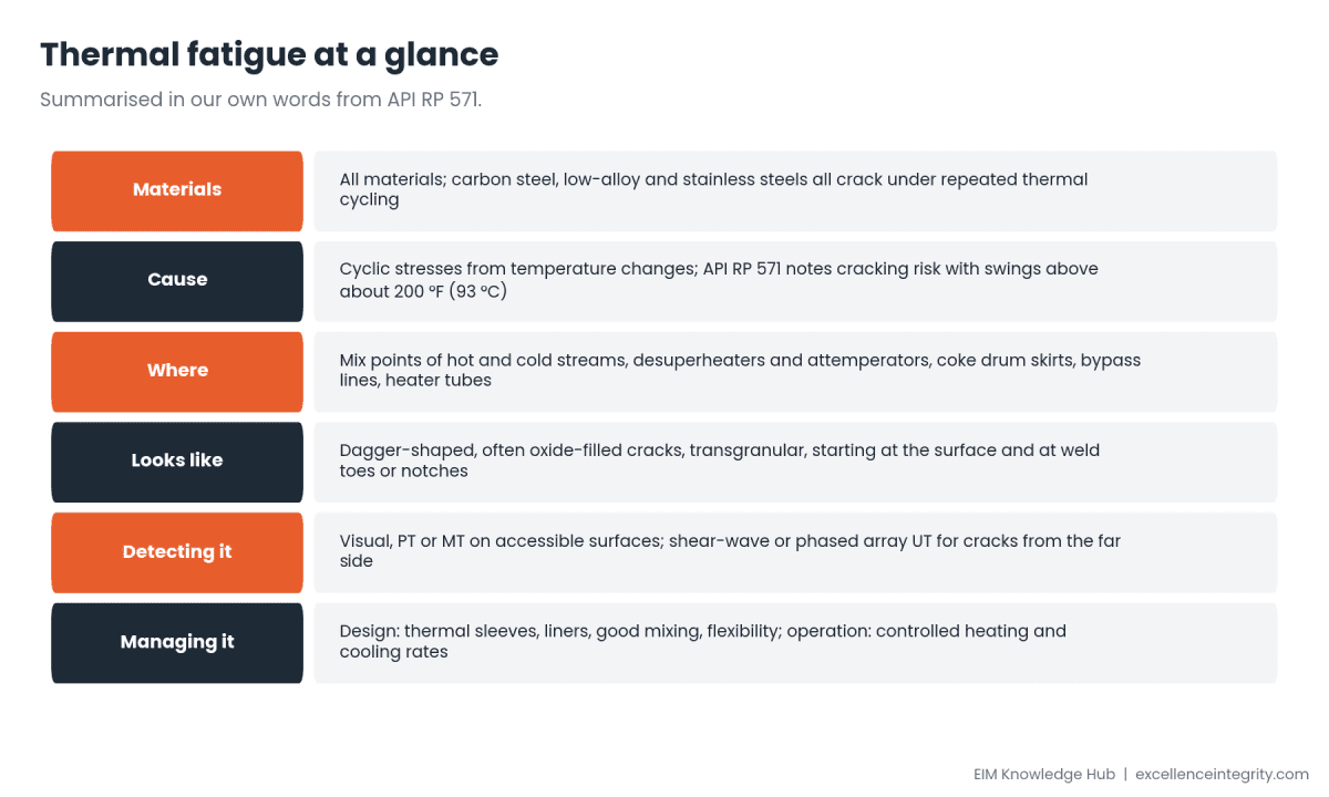
Week 6 of our Damage Mechanism of the Week series covers a mechanism that is all about change. Thermal fatigue cracks equipment not because it is hot or cold, but because it keeps switching between the two. Mix points, desuperheaters and coke drums are classic victims.
Short answer: Every time metal heats and cools unevenly, it expands and contracts against itself, creating stress. Repeat that enough times and cracks start, usually at the surface and at stress raisers such as weld toes. API RP 571 notes the risk when temperature swings exceed about 200 °F (93 °C). Prevention is mainly about design (sleeves, liners, mixing, flexibility) and operation (controlled heating and cooling).
At a glance
Why temperature swings crack metal
When part of a wall heats or cools faster than the rest, the hot part wants to expand and the cold part resists. The resulting stress can be high even at modest temperatures. One cycle does nothing visible; thousands of cycles grow cracks. Thick sections, sharp geometry and restraint make it worse.
Where it strikes
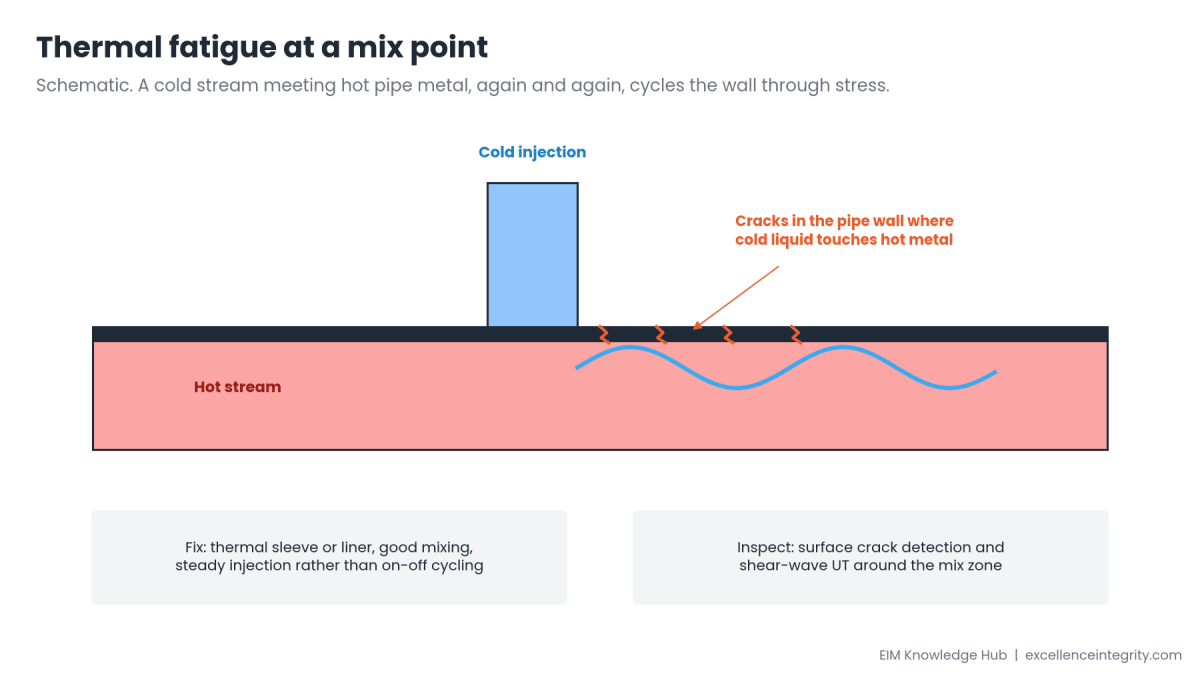
- Mix points where hot and cold streams meet, especially with intermittent injection.
- Desuperheaters and attemperators that spray water into steam.
- Coke drums, particularly the skirt-to-shell junction, cycled every few hours.
- Bypass lines and valves that open and close.
- Heater tubes and boiler components with frequent start-ups.
What it looks like
Thermal fatigue cracks are typically wide at the surface and taper inward, dagger-shaped, often filled with oxide. They are usually transgranular and may appear as a network or as parallel cracks. They often start at weld toes, notches and changes in section.
Detecting and preventing it
- Inspect: visual, PT or MT at accessible surfaces; shear-wave or phased array UT for cracks starting on the inside.
- Design: thermal sleeves or liners at injection points, good mixing, smooth transitions, flexibility to absorb movement.
- Operate: steady injection rather than on-off cycling; controlled heating and cooling rates on start-up and shutdown.
- Monitor: thermocouples at known hot spots show the actual cycles.
Learn more with EIM
Thermal fatigue is one of the damage mechanisms in API RP 571 (3rd edition), the body of knowledge for the API 571 certification. EIM is an independent training provider; API certifies inspectors. EIM's self-paced API 571 preparation includes a question bank, practice mode with explanations, timed mock tests, study notes and flashcards, with one year of access, and EIM's live API 571 Damage Mechanisms - Exam Preparation course with Mr. Deepak Rawtal runs weekend batches. See the API 571 page This post is part of our weekly Damage Mechanism of the Week series.
Frequently asked questions
What causes thermal fatigue?
Repeated stresses from uneven heating and cooling, which crack metal over many cycles.
Where does thermal fatigue occur?
At mix points of hot and cold streams, desuperheaters, coke drum skirts, bypass lines and heater tubes.
What temperature swing is a concern?
API RP 571 notes risk when swings exceed about 200 °F (93 °C), though geometry and restraint matter too.
What do thermal fatigue cracks look like?
Dagger-shaped, often oxide-filled, usually transgranular cracks starting at the surface, often at weld toes.
How is it prevented?
By design (sleeves, liners, mixing, flexibility) and operation (steady injection, controlled heating and cooling).
Sources
- API RP 571, 3rd edition: thermal fatigue. Summarised, not quoted.
- Checked 7 October 2026.